This series of texts describes how to carry out a familiarisation inspection of a sailboat. The first text described how to think about inspecting three of the nine fundamental components of a sailboat: the hull, the engine and the rigging. The second text, this one, illustrates how I familiarised myself with these elements when I started sailing two Contessa 32s in the spring of 2025.
The Contessa 32
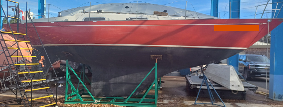
The Contessa 32 is a fibreglass sailboat with a central keel and no fin. It has a skeg hung rudder. The yacht’s specifications are given below.

- Length overall: 32 feet (9.75 m);
- Length at waterline: 24 feet (7.3 m)
- Main beam: 9.5 feet (2.9 m);
- Draft: 5.5 feet (1.68 m);
- Air draught: 41 feet (12.5 m);
- Hull speed: 6.6 knots;
- Diesel tank capacity: 60 L;
- Fresh water tank capacity: n/a.
- Gross tonnage: 6.9 gt.
- Displacement: 4.05 t.
Their hull structure makes them relatively easy to manoeuvre. Experience also shows that they are relatively ‘stiff’ yachts. Their centre of gravity is very close to the keel and the moment of return to equilibrium is large (stability is discussed below). Combined, this makes them safe and easy to handle when under sail.
Hull and through-hull
Performance
The hull is made of fibreglass reinforced with polyester resin. The main hull comprises at least seven layers of fibre. Typical of 70s construction, it is overbuilt. The central keel makes the yacht easy to manoeuvre at low speeds (… much more so than the Alberg 30!). Because the hull is relatively inclined at the bow, the boats cut through the water well in heavy weather. They are relatively comfortable. On the other hand, their wind drift is greater than that of full-keel yachts.
Through-hulls

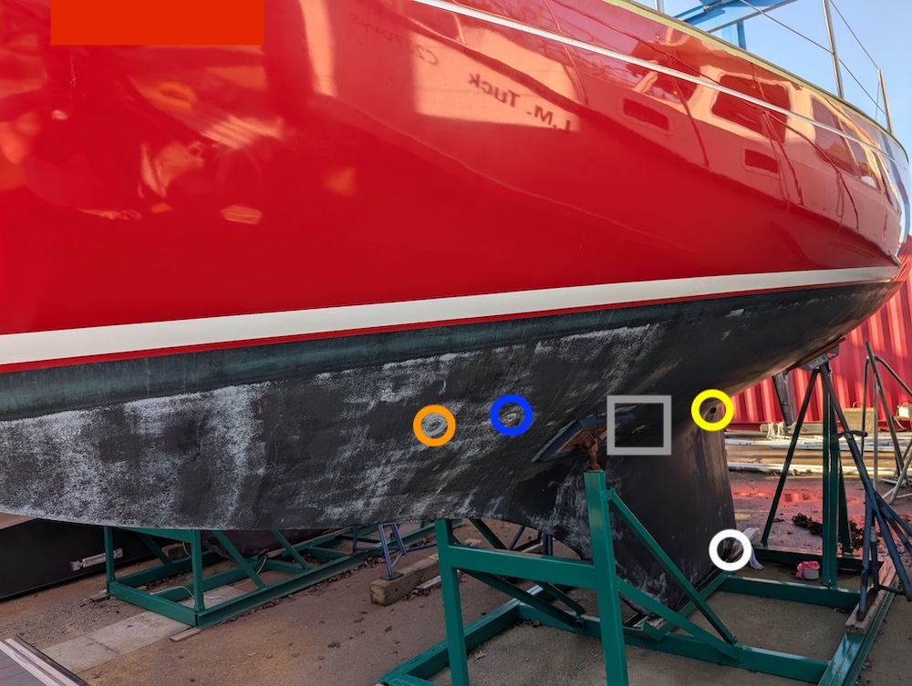
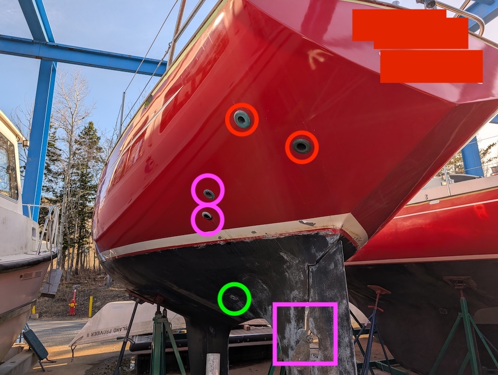
There are 12 through-hulls, two instruments passing through the hull, and a stern tube, for a total of 15 points of possible water ingress. The first fourteen are shown in the image above. The stern tube is located just before the tiller shaft. The photos below show the locations, seen from the outside.
- Starboard bow (brown): black water outlet (toilet).
- Port bow (blue): toilet water inlet.
- Port bow (orange): toilet sink drain.
- Port centre (orange): galley sink drain.
- Midship centre (yellow): engine water inlet.
- Centre midship (black): bilge hatch (located at the base of the keel, in white in the photo).
- Port aft (mauve): bilge pump outlets (one per pump).
- Port aft (mauve): bilge pump outlet (one per pump).
- Port aft (red): engine exhaust outlet.
- Aft port (red, closer to the stern): exhaust outlet blocked.
- Aft port (green): cockpit drain.
- Aft starboard (green): cockpit drain.
- Port centre (grey square): loch.
- Port centre (grey square): depth gauge.
- (Unillustrated): stern tube.
Most of the through-hulls are on the port side. In the absence of clear information about a possible a water ingress, manoeuvring on port tack is a good ‘blind’ technique that will in all probability reduce an ingress of water.
Otherwise, it is good practice to double-check that the bilge hatch is properly closed before launching.


Nables
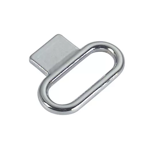
There are three fittings on the Contessa: one for diesel, one for drinking water and one for pumping out the black water tank. All three are on the port side and the plugs indicate their functions. To open each one, you need a standard bilge spanner. It would be unwise to leave without a fitted key (or a large screwdriver). For service purposes (diesel supply or fresh water), you should berth on the port side.
Bilge and bilge pumps

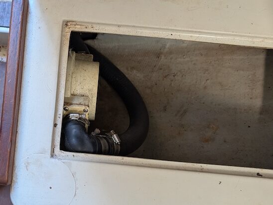
The Contessas hold is fairly deep (photo above). It runs all the way to the bottom of the keel, joining the bilge through-hull. A torch is required for routine inspection.
Each yacht has two manual bilge pumps. One is inside the boat, in the saloon. It is the most powerful. The other is in the cockpit. Each comes with a specific lever so that you can use it. Leaving without these levers would be very unwise.
The image above shows access to the bilge from the centre of the galley. The (very dirty) white hose is the bilge pump hose from the cockpit. The green hoses correspond to the bilge pump inlet and outlet in the saloon. In the centre, you can see the feed-through for the engine cooling system (in the closed position).
Below, the picture shows the bilge pump in the saloon, under the starboard seat next to the sink.
Stability

Contessa 32s are stable vessels. The figure on the right shows their static stability characteristics (Calder and Beeson, 2015).
The righting lever (GZ) increases sharply with the initial angles of heel, reaching a maximum moment of 80°.
There is also a high area under the curve, summarising the total moment of force that the vessel can exert when faced with an “extreme” heel.
In addition, the angle of reversal is 157°, meaning that the ship has to be practically upside down for it to capsize. Finally, the inverted stability of the capsized vessel is excessively low, meaning that the chances of it rolling over on its own in the conditions in which it capsized are fairly high.
In terms of form, the Contessa is a safe vessel. A useful test is to board the boat on the windward side, from the quayside, to see how much the additional weight of a person generates a list. On similar boats (e.g. Alberg 30), the exercise can induce a heel of 5° (softer boats). With the same exercises, the Contessas barely move.
The downside of such rigidity is that the return to balance can be abrupt. As a result, these yachts can make you seasick.
Drive train

Each yacht is fitted with a Bukh DV29RME two-cylinder engine. The engines develop 20 horsepower (15.4 kW). These are the engines fitted to the gravity-launched lifeboats on most cargo ships. Their technology is simple, with mechanical valve timing.
The engines are particularly ‘square’ (vibrating roughly). This characteristic is particularly apparent at start-up, when the engine is cold and there is air in the diesel inlet.
Cooling
These are water-cooled engines. Their design is such that the water circuit is normally closed and passes through the keel. They have been adapted for the Contessa. The water circuit is modified to be cooled by an open circuit. The water is drawn in at the keel, passes through a heat exchanger above the engine block and is then mixed with the combustion smoke to be discharged through the aft through-hull (via an anti-return system).
The water cooling system on the Contessa has only a rudimentary filter at the keel. There is no internal filter, and the cooling pipework is rigid and relatively small. As a result, the cooling system can become blocked. Each engine is fitted with an overheating alarm, and the engine must be shut down when switched on. The alarm indicator is right next to the ignition key.
The engine has a 2.94:1 front and 1.95:1 rear drive, connecting the engine shaft to the propeller shaft. The propeller is twelve inches long, with two blades, which means that the engine is overpowered for the size of the propeller. At rated power, the propeller will perform less well than at lower power. In addition to this general rule, the use of appropriate revolutions can be learnt by manoeuvring.
It is worth remembering the most important truth about sailboat engines: they are auxiliary engines, intended for docking or manoeuvring without sail. Engines are not strong enough to counter the effect of the sails in all situations and therefore cannot be used to take over a manoeuvre against the wind when the sails are set.

Useful components of the engine block
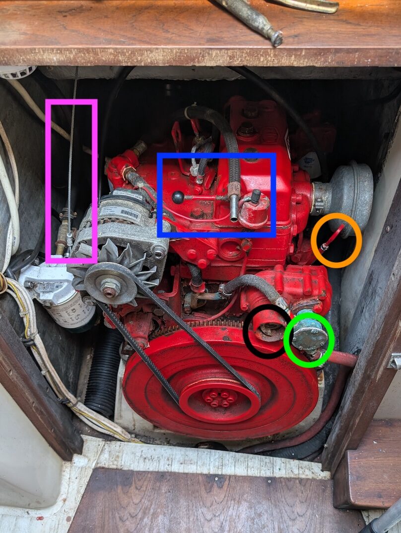
The image below illustrates some of the engine components that a skipper should be familiar with. Firstly, the image shows the position of the engine, under the cockpit, in the centre line of the yacht. Access to the engine is mainly by removing the steps from the companionway to the saloon. The figure illustrates this access, where the steps have been removed.
The pink box corresponds to the engine emergency stop mechanism. This is a cable that runs into the cockpit (outside, see next section) and allows the engine to be switched off in an emergency.
An interesting feature of the Bukh is that it can be started manually. The black circle corresponds to the receptacle for inserting the starting crank (which is not in the picture). This receptacle goes hand in hand with the cylinder depressurisation lever (framed in blue). It would be unwise to leave the navigation without the manual start crank.
Other features include the oil sump dipstick (circled in orange) and the impeller pump (circled in green). The engine’s alternator can also be seen between the stop mechanism and the cylinder depressurisation lever. Finally, note that the engines on the Contessa have modified air intakes (grey cylinder) compared to the standard models
Spare parts usually include a belt, an impeller and sacrificial anodes (adapted to the engine).
Diesel consumption
The diesel consumption curve as a function of revolutions per minute is illustrated below. Assuming hull speed is reached at 2400 RPM, the Contessa’s approximate consumption is 265 grams per kilowatt-hour. Given the 15.4 kW power of the engines and a diesel density of 0.840 kg/L, diesel consumption is 4.08 kg/h or 4.85 litres per hour.

Assuming a 60-litre tank and the usual fuel distribution (⅓ outward journey, ⅓ return journey, ⅓ emergency), the engine range is detailed in the table below.
| Range | Hours | Surface nautical miles. |
| Outbound | 4.1 | 27.2 |
| Return | 4.1 | 27.2 |
| Emergency | 4.1 | 27.2 |
Note: the range in nautical miles assumes that hull speed has been reached.
Propeller pitch
The propeller pitch is on the right (standard). This means that when going astern and at low speed (berthing), the propeller pitch will push the bow to port. You need a minimum of speed to manoeuvre in reverse. That said, Contessa 32s are much more manoeuvrable in reverse than full-keel vessels.
Rigging
Standing rigging

My familiarisation with the Contessa 32 included the responsibility of adjusting the standing rigging at the start of the season. I relied on the Selden mast rigging adjustment guide, which is very well done. It describes very well the keel stepped and single spreader configurations.
The Contessa 32 does not have an adjustable backstay. Combined with the standing rigging configuration, this means that the tension adjustment is the same in all directions. This allows you to concentrate on the mast rake, which should be between 6″ and 9″ aft if you want a safer environment rather than a sporty one.
Mast rake

Mast rake is the horizontal distance between the gooseneck and the end of a lead line running from the top of the mast down to the gooseneck. This is an indirect measure of the angle between the mast and the bow.
For the Contessa 32, acceptable mast rake values are between 6 and 9 inches, i.e. an angle of between 0.8° and 1.2° measured from the top of the mast.
The mast rake is measured by hanging a heavy object (a 4 litre can of engine oil works very well) from the mainsail halyard. You can then measure the distance between the mast and the halyard with a tape measure. In practice, this distance varies with the waves hitting the hull, so you need to be patient when measuring.

On the Contessa 32, the standing rigging is made up of 1×19 stainless steel cables 7/32 inches in diameter. The maximum breaking strain is around 29.6 kN (3000 kg), i.e. 6600 lbs of pressure. A load of 15% corresponds to around 990 lbs.
The tension in each of the cables was thus organised so that the mast was balanced (no ‘S’ or ‘C’ bend) and the tension on the tensiometer was in the 960-1200 lbs range (the difference between the two ends of the range is half a turn of the rigging screw!).
I tested the adjustments again after one or two sea trips (to my great delight, with no changes!).
Sail-rigging interface
Only three bumps go through the boom: two reefing bumps and one tacking bump. The mainsail is only held in place by its tack points and the sliders. It is not wired to the boom, which means that the camber of the foot can be adjusted. The gooseneck has hooks for reefing. The mast has a small slot, which can be undone with a screwdriver, for inserting the mainsail sliders. Use shows that they block the slides when the mainsail is hoisted.
Running rigging
The running rigging is typical of a sloop-rigged yacht. There are six winches, four on each side of the cockpit (for the jib and a possible spinnaker). The other two are on deck for the halyards (starboard) and the bosses (port). There are four halyards on the yacht, one for the mainsail and three for the headsails (jib, spinnaker and spinnaker pole). The topping lift is on the mast. The mainsheet is on the traveller (and slightly too short).
Three bumps are brought back to the cockpit, the first two reefs of the mainsail and the jib furling line. The third reef is taken manually. Notably, the first reef line is not long enough to reach the third attachment point, so if a third reef is required, the second line must be detached and attached to the third.
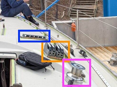
The running rigging brought back to the cockpit passes through a rhea system fixed to the deck. Halyards and lines are run through pianos. Genoa sheets are generally attached to winches.
In the photos above, the image on the left shows the starboard rheas (framed in blue) used to redirect the running rigging (not installed), the piano (framed in orange) and the winch reserved for the halyards (framed in pink).
Sails and sailing performance
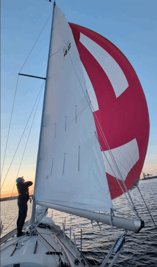
Both yachts are equipped with custom-made sails. The mainsail is semi-battened, heavy-weight (thick) and allows three reefs. There are three headsails for both yachts: a 110% jib, a 130% jib, a storm jib and a spinnaker. The headsails are shackled (no furlers) and you have to practise changing the sails at sea if you’re planning long passages.
On line, I found a polar speed curve (image below). They indicate a maximum speed of around 6.5 knots for winds of 20 knots. In terms of speed, the optimum performance is between beam and beam. However, the curve shows that the boat’s maximum speed is less than its hull speed, which is 7.3 knots (1.34\sqrt{30} \approx 7.3).
The experiment shows that the hull speed is a better measure of the boat’s maximum speed than the polar curve found online (even with 15 knots of wind). This means that the polar curve needs to be scaled up.

The polar curve also reveals effective tacking techniques. The sailboat’s speed deteriorates rapidly as it approaches the wind beyond the small beam, with the boat making less than 4 knots. In fact, if you want to sail upwind, the effective angle of tack, maximising speed at the target (ang.: velocity made good), is between 40° and 41°. Beyond that, the increase in distance is greater than the increase in speed. Below this, the reduction in speed is greater than the reduction in distance.
In downwind conditions, there is no performance gain from diverging from the required direction.
Conclusion
The above familiarisation puts into practice the recipe presented in the first text. It focuses on the engine, hull, rig and sails. It seeks to identify what can be done with the boat as it is. It’s not an examination of values, of repairs to be made, but focused on use.
In the next two texts, I’ll continue to detail how to familiarise yourself with the onboard systems (electronics, toiletry, life on board, etc). The third text will deal with the ‘generic’ recipe and the fourth text will apply it to the same Contessa 32 as in this text.