This is the third in a series of articles on celestial navigation. It focuses on the use of the sextant. Specifically, it covers how to:
- take a sextant reading;
- read a Vernier scale;
- measure an index error;
- check the perpendicularity of the sextant’s mirrors.
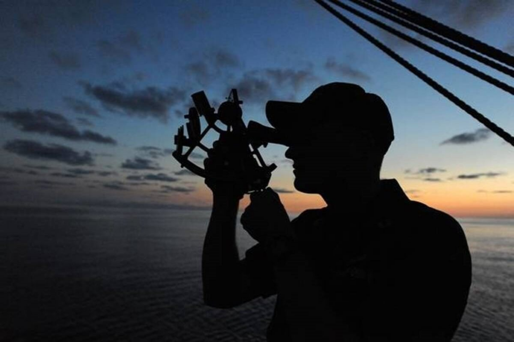
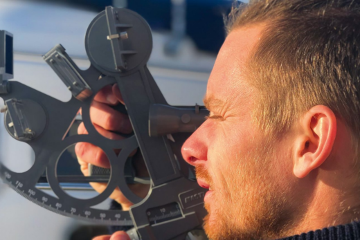
Taking a sextant reading is the most practical part of celestial navigation. It is also the most romanticised, the most frequently depicted in images and films featuring navigation. It is the part everyone imagines when they want to take a course in astronomical navigation. The part where you are out on deck, with the sextant in your hands, and where you seem to be questioning the universe to determine your position.
In practice, this part takes five to ten minutes.
Taking a sextant bearing
Basically, a sextant is nothing more than an angle protractor. It is of higher quality than those used in primary school, and two mirrors are added to specialise it for measuring celestial bodies, but the measurement remains an angle between two objects. Specifically, a sextant measures the angle between the Earth’s horizon and a given celestial body. This angle is called the altitude of the celestial body (denoted by H).
A sextant consists of a telescope and two mirrors. The first mirror is fixed, whilst the second is movable, attached to the index finger to allow angles to be measured (image below).
The second mirror fully reflects the light it receives. As for the first mirror, there are two types, varying depending on the sextant model.
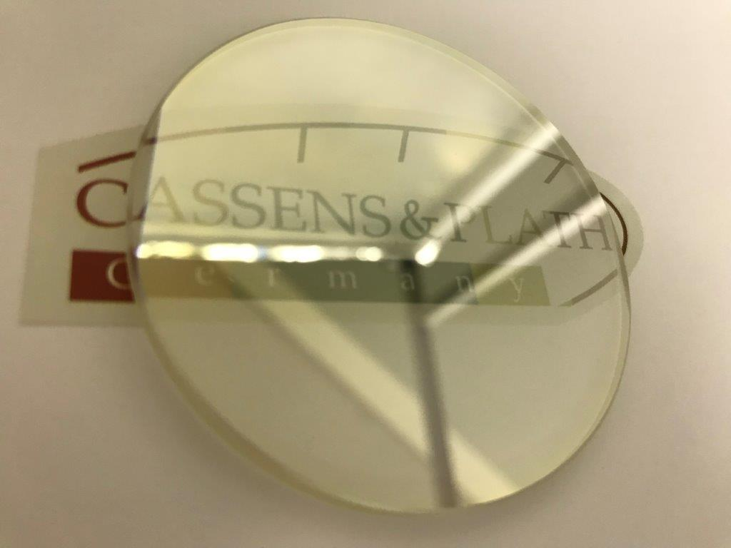
The first type of mirror occupies half the space covered by the sighting tube. Thus, on the side occupied by the mirror, one can see the reflection of the celestial body. On the uncovered side, one sees directly ahead.
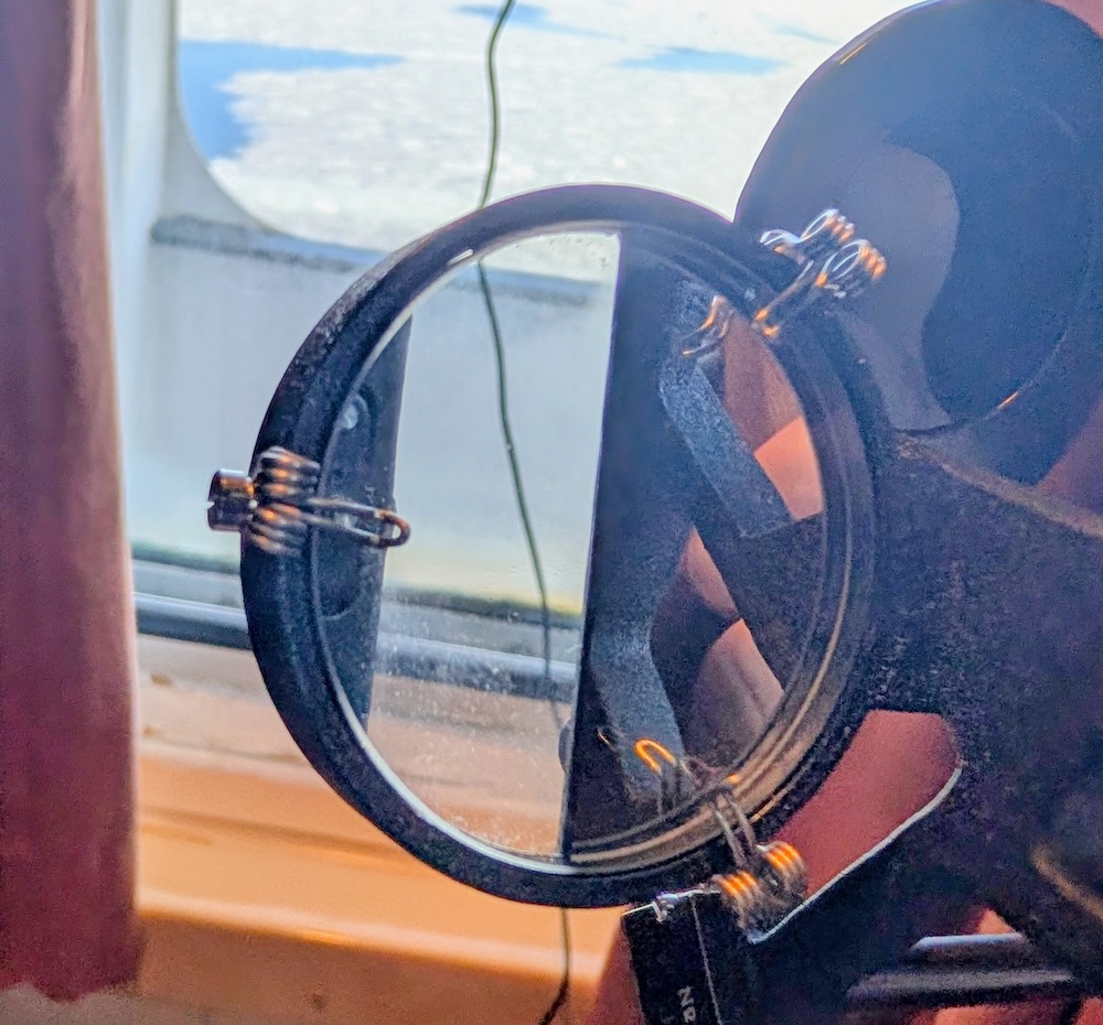
The second type of mirror occupies the entire viewing area but is semi-transparent. This allows the reflection of the celestial body and the horizon to be seen across the entire scope. Below, the image on the left shows a mirror occupying half the scope, whilst the image on the right shows a semi-transparent mirror.
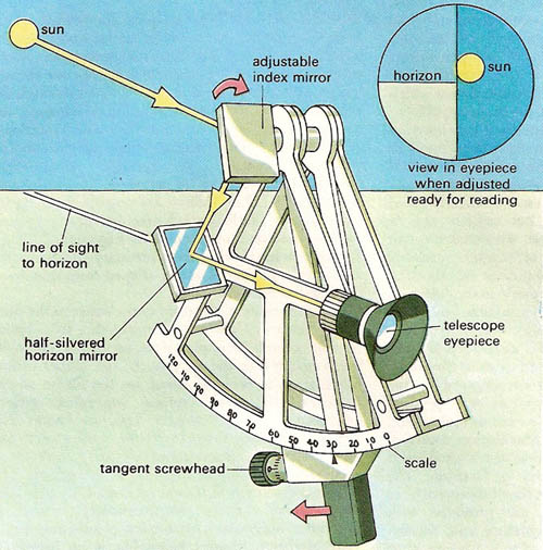
Combined, the two mirrors allow the horizon and a portion of the sky corresponding to the angle set by the sextant’s index to be seen simultaneously. By adjusting the sextant’s index, the visible portion of the sky is altered. If this portion includes a celestial body useful for navigation, one can then align that celestial body with the horizon to obtain a height.
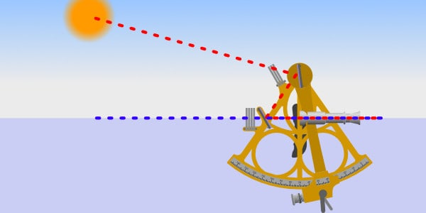
To obtain the altitude of a celestial body, one must point the sextant in the direction of the star, sight the horizon, then sweep the sky roughly by moving the index using the adjustment clamp. If you aim in the right direction, the celestial body will appear in the eyepiece. Once the celestial body is in the eyepiece, you must refine the height measurement using the adjustment knob. This allows the second mirror to be moved slowly and precisely. When the celestial body is aligned with the horizon, you then have an accurate measurement of its altitude.
Below, the image on the left shows the sun visible (through a filter) in the right-hand part of the telescope. The left-hand side shows the horizon – well, almost – as it was too bright for the camera that took the photo. The image on the right shows a simplified telescope at the top right of the image. You can see that the lower part of the Sun is aligned with the horizon.

Sextants are fitted with filters to reduce the intensity of the transmitted light. If the target celestial body is the sun, it is essential to use a filter to avoid damaging your retina. If the horizon is particularly bright (due to snow or other factors), you can also place a neutral density filter over the horizon to achieve better contrast with a star. The cardinal rule is to protect your eyes when the light is too intense. For the rest, experimentation is a good guide to finding what works.
Reading a Vernier scale
The main scale on a sextant is in degrees. It is this scale that the index finger sweeps across. However, a second scale is visible on the adjustment wheel. Depending on the model (and price) of the sextant, this scale may be accurate to the minute, to a fifth of a minute, or even to a tenth of a minute.
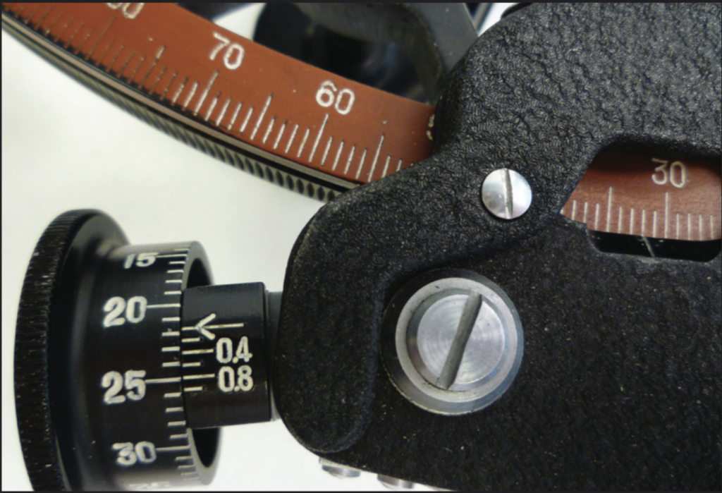
On the Tamaya illustrated in this text, the scale on the moving part of the adjustment wheel (on the left) allows you to read the minutes. The scale on the fixed part of the dial (on the right) allows you to read the fifths of a minute (0.2′, 0.4′, etc.). Together, these two parts are known as a Vernier scale. Most sextants are fitted with this type of scale.
To read a Vernier scale, you must first read the whole degrees on the main scale. This is the part indicated by the index. The white line on the index indicates the whole degree measurement. You must note the last whole degree to the left of the index.
Next, read the minutes on the left-hand side of the vernier wheel. Note the last full minute at the top of the base line (to the right of the vernier wheel).
Finally, to obtain accuracy to the nearest fifth of a minute, you must check which mark on the scale to the right of the dial is aligned with any mark on the left-hand side of the dial. The scale is designed so that there is only one aligned mark.
- If the base line is aligned, this means there are zero fifths of a minute in our measurement.
- If the first mark is aligned, there is one-fifth of a minute (0.2′).
- If the second line is aligned, there are two-fifths of a minute (0.4′).
- And so on.
Two examples
The image on the left below shows an elevation of 66° 37.2′:
- On the main scale, the number of whole degrees to the left of the index is 66°;
- On the dial, the number of whole minutes above the base line (marked with a dot on the Tamaya) is 37′;
- To the right of the dial, there is a fifth of a minute to be added, as the first line is aligned with a line on the left-hand side of the dial.
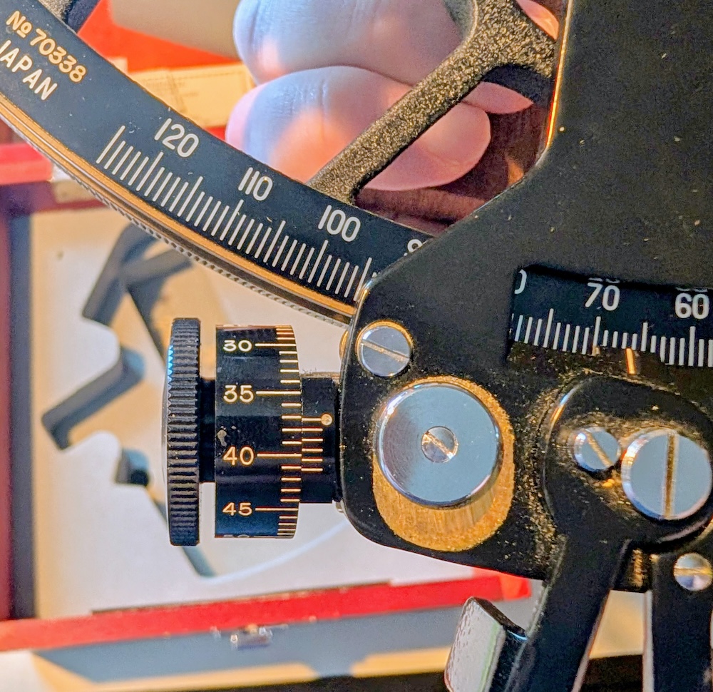
In the image on the right, the reading should be 41° 27.8′:
- On the main scale, the number of whole degrees (to the left of the index) is 41°;
- On the dial, the number of whole minutes is 27′;
- To the right of the dial, the fourth bar on the right-hand side is aligned with the dial on the left, indicating an additional 0.8′.
Measuring an index error
The perfect sextant
With a perfect sextant and the index aligned at 0° 0.0′, the image transmitted by the second mirror should correspond exactly to what is in the sight of the telescope:
- On sextants with a mirror occupying half the telescope, what is seen on the left should extend into the right-hand side without any break.
- On sextants with a semi-transparent mirror, there should be no blurring: what is reflected should correspond exactly to what is behind the mirror.
In other words, when the index is at 0° 0.0′, a perfect sextant should show a uniform image of what is being sighted through the telescope. This is the case when the mirrors are perfectly aligned. In this case,the index error is said to be zero.
The imperfect sextant
For various reasons, a sextant may be imperfect. The image below shows an example of a telescope where the mirrors are not aligned. A black line can be seen on the left-hand side of the telescope. If the mirrors were correctly aligned, the left-hand side would continue seamlessly into the right-hand side (from the second mirror). However, the extension of this black line is lower down, reflecting the fact that the second mirror is not aligned with the telescope. (Note that the photo is an exaggeration to illustrate the concept of a ‘break’.)
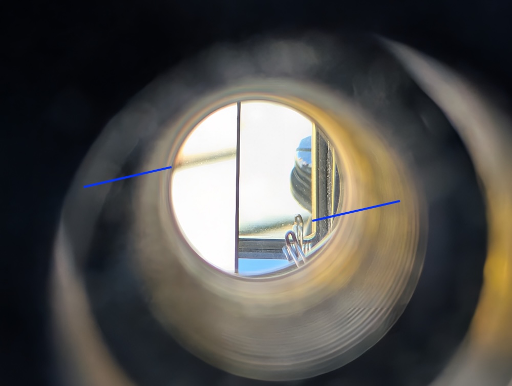
On an imperfect sextant, the index must be moved to a position other than 0° 0.0′ to obtain a clear sight (without a break or blurring). The angular value of the shift corresponds tothe index error. This is the angular shift required to align the image seen through the eyepiece. A typical index error can range from 0.5′ to -0.5′.
To find the index error, aim at a point on the horizon containing a well-defined horizontal object (e.g. a bridge or the horizon). You must then adjust the knob until the view is clear. For mirrors covering half of a telescope, this means there is no visible break. For transparent mirrors, this means that blurring is minimised. You must then read the vernier scale to determine the index error.
This error is important for determining the correct position of your vessel. Compensating for the index error is the first correction we cover. A positive index error means that this error must be subtracted when calculating the altitude of a celestial body. A negative index error means that this error must be added to the altitude of the celestial body. If this is not taken into account, the instrument’s error is incorporated into our position.
We saw in the section on the theory of celestial navigation that each minute measured with the sextant corresponds to 1 nautical mile on a position circle. An index error of 0.5′ that is not taken into account therefore amounts to an error of about one kilometre!
Two examples
Example 1: You have obtained a celestial body altitude of 41° 27.8′, but you know that your sextant has an index error of -0.5′. What is the celestial body altitude corrected for the index error?
Solution: as the error is negative, we must add. This gives us a corrected altitude of 41° 28.3′.
Example 2: You have obtained a celestial altitude of 66° 37.2′, but you know that your sextant has an index error of 0.2′. What is the celestial altitude corrected for the index error?
Solution: As the error is positive, we must subtract. This gives us the corrected altitude of 66° 37.0′.
Checking the perpendicularity of a sextant
It is good practice to check that the mirrors are aligned before taking a reading, particularly if the sextant has not been used for a long time. Checking the alignment of the mirrors is known as checking for perpendicularity. If the mirrors are not perpendicular, there will most likely be an index error. Conversely, an index error may indicate that the mirrors are not perpendicular. As there are two mirrors, two checks must be carried out.
Checking the second mirror
You must start with the second mirror, as its check depends solely on its alignment. (Checking the first mirror requires the second to be aligned.)
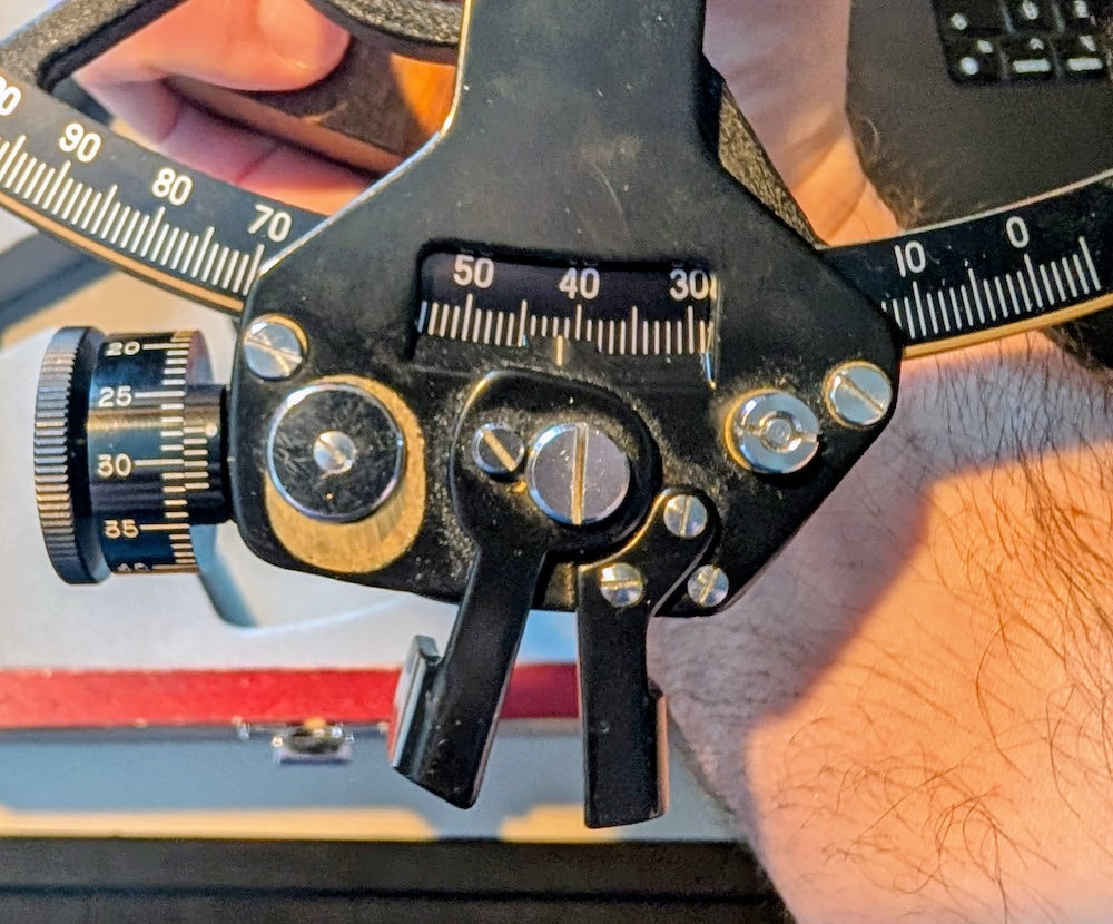
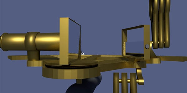
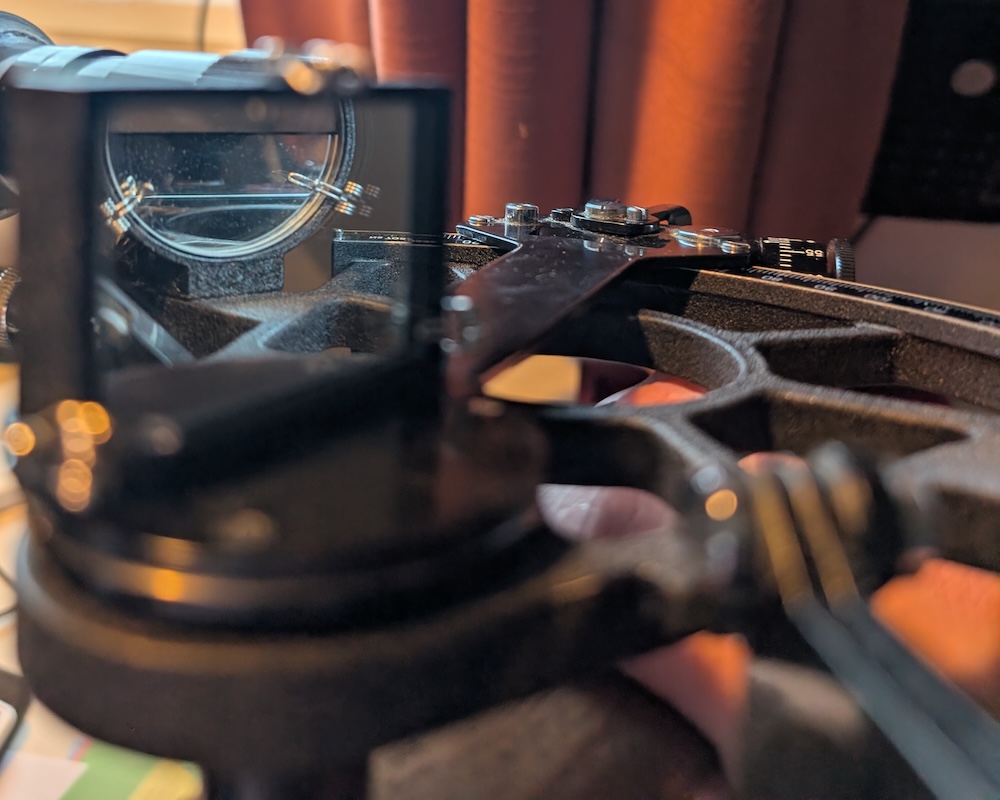
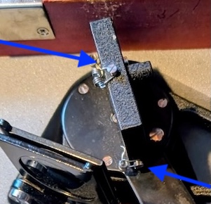
To carry out the check, position the sextant so that you can see both the mirror and the main scale simultaneously from the top of the instrument. The image above shows the view of the person carrying out the check.
You must then move your index finger so that you can see the main scale simultaneously with the naked eye and through the second mirror. If the extension of the scale between the mirror and the real world is unbroken, then the mirror is aligned. Otherwise, you must adjust the angle of the mirror.
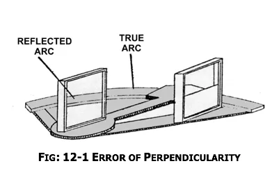
There are two images below. The one on the left shows an aligned mirror. The one on the right shows a mirror that is not aligned.
Checking the first mirror
The first mirror is checked second, as we must ensure the second mirror is aligned before carrying out the second check. Otherwise, we would be trying to correct the combined error of two mirrors with just one!
This second check is very simple: set the index to 0° 0.0′, then adjust the position of the first mirror until the sight is clear (no break, no blurred image). When the sight is clear, you know that the first mirror is aligned.
How do you adjust the mirrors on a sextant?
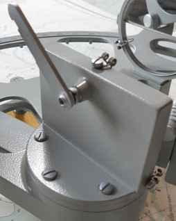
As a general rule, the mirrors have screws that allow for minor adjustments (see photos below). On some models, these screws can be turned by hand. On higher-quality sextants, a specialised screwdriver is required. To adjust the mirror’s angle, turn the screws to correct the observed angular error.
Note that a screw that is too tight can damage a mirror, so care must be taken. As sextant models vary, it is best to follow the manufacturer’s instructions rather than these general guidelines.
Conclusion
Taking sextant readings is a practical exercise. Nothing beats practice. You need to go somewhere where you can see the horizon and practise taking readings. Your first readings will take time. The more you do it, the quicker you’ll get.
Even under the best conditions, sextant readings are subject to errors. We have covered one correction in this text, namely the correction for the index error. The purpose of the following text is to apply the other corrections that will be applied to the altitude reading from the sextant (noted H_s) to the one usable for determining a position, namely the observed height (noted H_o).
Ultimately, you will have angles, each measuring the distance between the horizon and a celestial body. You must then understand the theory and perform calculations to convert these angles into the ship’s position. The calculations that follow are a little less fictionalised!
Did you enjoy this text? You can read more in the Learn section of this site.


5 Responses
[…] It deals with the corrections to be made to observations taken with a sextant. The text on how to take observations with a sextant should be read […]
[…] It deals with the corrections to be made to observations taken with a sextant. The text on how to take observations with a sextant should be read […]
[…] essential tools and documentsThe theory of AstronavigationHow to do and read sextant sightsCorrections to sextant sightsFinding the GP of a Celestial BodySpherical Triangles and Sight […]
[…] the start of the identified time window, you must begin taking sextant readings. You must simultaneously note the identified altitude and the time (accurate to the second!). It is […]
[…] to use a sextant is covered in a full text. There’s no need to spend 1000$ to get started. If you become a professional navigator, chances […]