Don’t get too concerned about highly accurate measurements (to two decimal places) – this is not aerospace.
Philip Locker
I am repowering an Alberg 30. This text is about useful knowledge that should be understood prior to a power train install. It reduces the installation time and saves money. It covers the topics of fiberglass, engine bearers, through-hull installations, rudder design and sterntube installation. This text is preceeded by part one, about the power train design, and part two, about project management. References are provided at the end of this part, but several references are also availlable in part one.
Fiberglass 101
The Fundamentals
In the United Kingdom, fiberglass is more aptly named « glass reinforced plastic » (GRP), which is litteraly what it is: fiberglass strands petrified in plastic.
Individually, both fiberglass strands and resins have weaknesses. Fiberglass strands are highly resistant along the strand, but break easily accross the fiber. Alone, the plastic is brittle and breaks under load. It is the combined force of the fiberglass and the plastic that gives fiberglass its solid mechanical properties (Elchakany, Yang and Pham, 2023).
The plastic used in fiberglass comes from resin, a chemically stable and viscous liquid. When the resin is combined with a catalyst or an hardener, the liquid becomes unstable and a chemical reaction occurs (often generating heat). Those interested in resins from an organic chemistry standpoint can read Wikipedia or CompositeWorld for a good summary (Wikipedia 1-3, n.d., CompositeWorld, n.d.). For the rest of us, the key point to remember is that resin is converted in solid plastic by mixing it with either a catalyst or an harderner. At the beginning of the curing process, which can last from minutes to hours, the resin is still liquid. During that period, one can mold several shapes of fiberglass before it solidifies.
It is also worth mentionning the obvious: neither plastic nor (fiber)glass rots, decays or corrodes. It is a very stable product. This is what led John Casey to write that « Wooden boats regularly die early deaths of natural causes; fiberglass boats must be assassinated. » (Casey, 2022).
When considering its strength, its ability to be shaped and its durability, it is understandable that fiberglass is the foundation of hulls and so many boat parts.
Fiberglass Strands
Fiberglass strands are usually organized like a fabric. They come in three basic forms: woven, chopped strand and combined. Woven fiberglass is such that the strands are knitted with a known pattern – most often perpendicular, similar to a chessboard – to increase its strenght in the direction of the pattern. In a chopped strand fabric, the fiberglass strands are chopped and peppered randomly in a layer of polystyrene. If truly random, it increases the strength in all directions. The combined fabric is the combination of both: one layer of chopped strand combined with one layer of woven. Woven fabrics can be made of larger strands, allowing for tougher layers of fiberglass, while the chopped strand fabric is made of smaller strands. The « size » of the strands are referenced by their weight per unit of surface area: 18 oz fabric, 10 oz fabric, 6 oz fabric, and so on. The higher, the stronger is the fabric… and the harder it is to shape in place.
That is the advantage of the chopped strand mat. Some resins dissolve polystyrene (the ester type described below), freeing the chopped mat strands during the application. It thus makes the strands much more pliable during the application and thus fits acute angles better. If one needs to fiberglass two perpendicular pieces of wood together, chopped strand mat would be a very well suited material. For structural work such as on the hull or on engine bearers, woven fiberglass is better suited.
I am not aware of commercial differences regarding fiberglass mats and strands. I think of it like spaghettis: there may be small differences through brands, but in general terms, the sauce is what differentiates one spaghetti recipe from another. For fiberglass, resin differentiates the final product much more than the fiberglass brands.
Resin Types
Resins can be classified in two categories: epoxy and the « ester » types such as polyester or vinylester. There are different chemicals within the « ester » category, but bunching them together is a good first approximation. The general qualitative properties of the two categories are summarized in the table below.
| Property | Ester types | Epoxy type |
| Price | Cheap | Expensive |
| Mechanical resistance | Weaker | Stronger |
| Ease of work | Easier to shape | Harder to shape |
| Bonding properties with other materials | Adheres only to ester resins | Adheres to all types of resins |
| Compatibility with gelcoat | Compatible | Not compatible |
| Volume stability | Shrinks while curing | Does not shrink while curing |
| Water permeability | Most are not water resistant | Water resistant |
| Smell | Heavy « chemical » smell | Light smell. |
Ester types work with a catalyst, which is added in terms of drops (e.g. five drops to a pint), meaning that the catalyst has a negligible impact on volume. A minimum quantity of catalyst is required for the reaction to occur evenly in the resin. Adding more, up to a maximum, can alter the time it takes for the chemical reaction to occur. In plain terms, adding more catalyst speeds up the process, up to a certain point. One can thus change the amount of catalyst to match some circumstances. For instance, temperature has an impact on the curing time (the hotter, the faster), so adding less catalyst during hot days can somewhat counteract the impact of the temperature. If a fiberglass job requires more time, adding the minimum amount of catalyst may give this needed time.
Epoxy resins work with an hardener, which must be added in proportions that substantially changes the volume (e.g. 3 parts of resin for 1 part of hardener). Thus, calculating the final required volumes must account for the hardener volume. The exact proportions will vary with brands.
The strength of each type of resins is pretty well documented. A reccuring statistic found on most product description is that epoxy resin is (roughly) 20% stronger than polyester resin, which is the main type of ester (BoatUS, 2012; SPSystems, n.d.; Mantavoni et al., 2017; Wikipedia – 3, n.d.; El Wazery et al, 2017). This is accurate for both tensile and compression strength. Along pretty much any dimension except the price, epoxy resins are superior. Perhaps the sole exception is when it comes to gelcoat, which is nothing but polyester resin with pigments. Because gelcoat is polyester in disguise, it does not adhere well to epoxy repairs. Interprotec, or other types of finishes, would be better suited, but if the use of gelcoat is an absolute must, then one binds itself to the ester family for better … or worse. It should however be noted that epoxy is water resistant and can be used as a « last coat » prior to painting.
Peanut Butter, Mayonnaise and Ketchup
Small jobs and repairs do not lend themselves to the use of fiberglass mats. A good example would be « fiberglassing » within drilled holes to avoid exposing the wood core. In no way a fiberglass fabric can enter a drilled hole, despite the need to protect the core from the elements. This is where « thickened epoxy » comes in play. For small repairs, it is the standard fiberglassing technique.
Thickened epoxy is epoxy resin with silica in powder form blended in the mix. The strands of silica are so small that they float in the air (and a mask should be worn when it is manipulated). The density of silica varies with the need: the more silica, the more the resin will behave like a solid. So when gravity is your ally, or when you must inject epoxy in small crevisses, less silica helps as the liquid form will fill it all. In any other case, more silica will turn the resin in a putty, which will help shaping it appropriately.
There is no doubt that the established nomenclature to describe densities is american. Densities, or consistenties, are refered as « peanut butter » (large amount of silica), « mayonnaise » (medium amount of silica) and « ketchup » (small amount of silica). The nomenclature conveys known (american) textures. For beginners, BoatWorks Today quantifies these textures in volume (table below), but they recognize that this is mostly to help get a sense of the textures rather than an hard rule.
| Consistency/Density | Silica per 150 grams of Resin |
| Ketchup | 11 grams |
| Mayonnaise | 15 grams |
| Peanut Butter | 22 grams |
Ester Family?
The three main types of resin in the ester family are polyester resin, vinylester resin and phenolester resin. The first resin is the main type, being used in boat construction, « puttys » and gelcoat. It is cheap and widely availlable. It is however less water resistant and, if used underwater, can cause blistering. Vinylester is chemically designed to be more water resistant and is slightly more robust than polyester. Phenolester is mainly used because of its fire retardant properties. Most often, phenol- and vinyl- esters must be ordered. In all likelihood, off the shelf ester resin is polyester.
Practical Knowledge and Techniques
The videos by BoatWorks Today are a good starting point for acquiring a practical sense of how fiberglass works. If you have time on hand, exploring the channel is very helpful. The channel has an experimental mindset and the lead person is a very good teacher. The video « How to Fiberglass Over Plywood » influenced me on how to think about fixing the engine bearers to the hull. In particular, the technique to smooth the angles, so as to ease the fiberglass into the shape, is a crucial technique to understand. Pre-heating the resin, as explained in the first video, is also of practical importance.
Engine Bearers Design
I call engine bearers the structural part of the engine room which supports the engine. Some write « engine stringers » and both should not be confused with the engine feet. In the three pictures below, the engine bearers are clearly shown in the first picture while the third picture shows one engine foot. Engine bearers are the hull extension that attaches the engine to the boat. For most boat, this is where the thrust from the propeller is transfered to the hull, moving the boat forward. As the engine can go back and forth in close quarters, the engine bearers must be structurally solid, enough to withstand several newtons (pounds) of force due to changes in the thrust direction.
I found four designs of engine bearers. The first one is more of a category and referes to custom fiberglass mold attached to the hull. I did not investigate those. The three other designs start with wood mounts fiberglassed into the hull. The differences between them stem from how the engine is fastened to the bearers. With the first design, the engine is through bolted in the wood (first picture below). In the second design, the engine is through-bolted on a 90° steel angle bar, itself through-bolted on the side of the wood bearers (second picture below). With the third design, the engine is bolted directly in the bearers with wood fasteners (third picture).
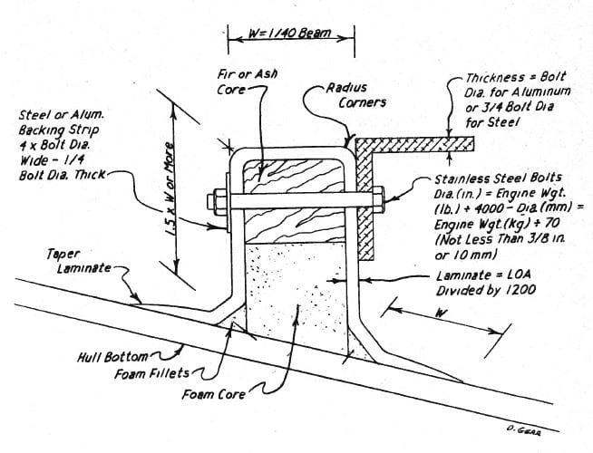
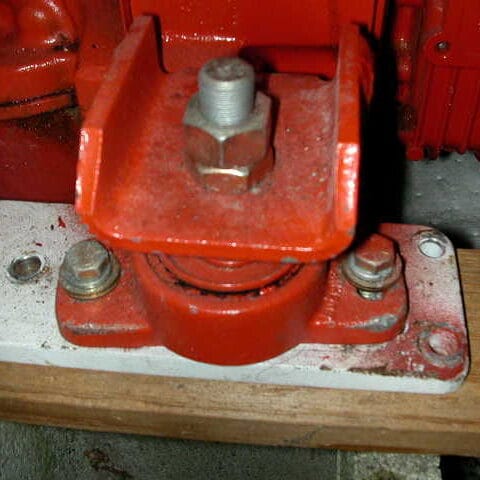
In my views, through bolting is superior to the use of wood fasteners (or lagbolts) because its the whole bolt and nut that holds the engine in place rather than the threads on the fasteners. There is less chance that the engine will detach from the bearers because of vibration. Compared to the 90° steel bar design, the first design is the most structurally sound: there is a minimum number of pieces and the engine sits on top of the bearers, reducing any lateral stress. However, the first design makes it harder to change a through bolt if it breaks. On the second design, because through bolts are accross the engine bearers, they can be replaced with ease. Likewise, the 90° steel bars can be replaced if they are fatigued. I would thus argue that the second design is easier for maintenance. However, because the engine sits in between the bearers, the bearers must be made smaller to fit in the engine bay. Furthermore, the engine generates a lateral force on the bearers, which increases the stress on the fiberglass holding the bearers. If it breaks the mechanical bond « sideways », then the bearers must be rebuilt from scratch.
The first design is the hardest to implement as the position of the engine feet must be known exactly prior to the install. This may be a good replacement if the same engine is used and if it is known where it stands in relation to the shaft. Starting from scratch with a new power train would however rely on theoritical measures to make it work, which is a risk. The second and third designs are structurally similar and allow for drilling the holes once the engine is in place. They are thus easier to implement. However, the second design requires thinner bearers and so, more precision as to where they should be fiberglassed in the first place. In contrast, the third design allows for wider bearers and thus, more sideways manoeuver for engine alignment. It further supports the engine load straight from the top. Thus, the only weak point of the third design, compared to the first one, is the use of wood fasteners. It also has the advantage of being easier to implement. Because there was no engine prior to the install, I used the third design.
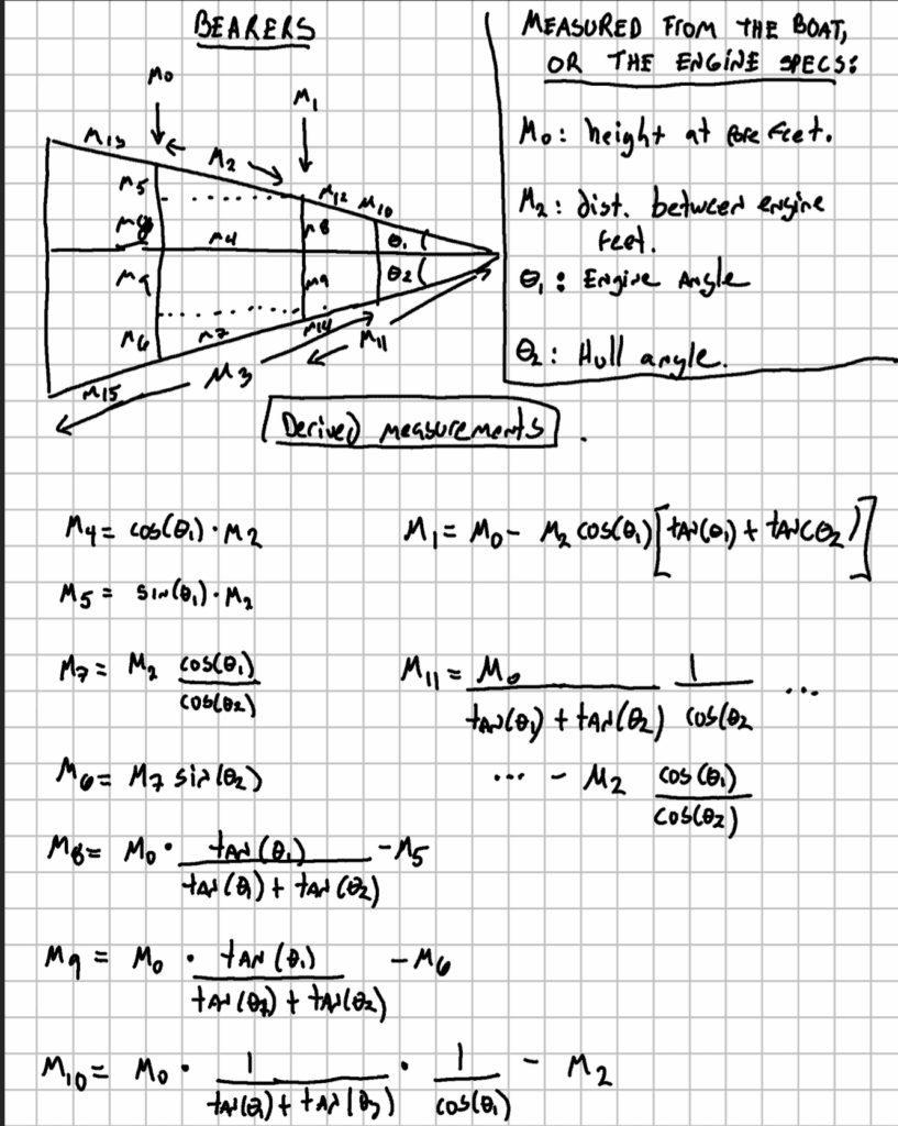
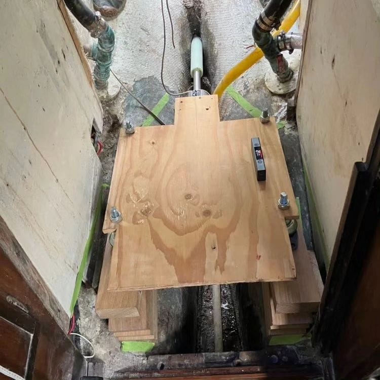
I knew from previous analyses that the engine would sit at an angle of roughly 11° down bubble. I designed the engine bearers using a laser protracter so as to fit this measure, pointing down at the sterntube hole (picture below).

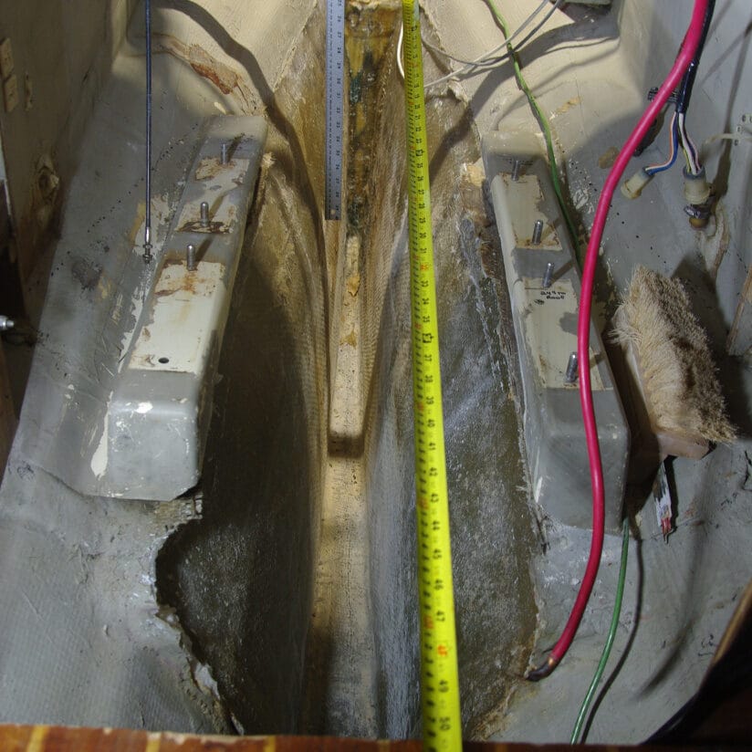
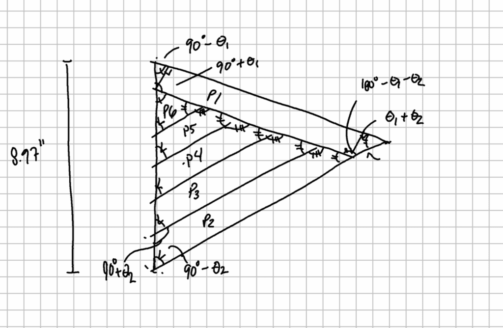
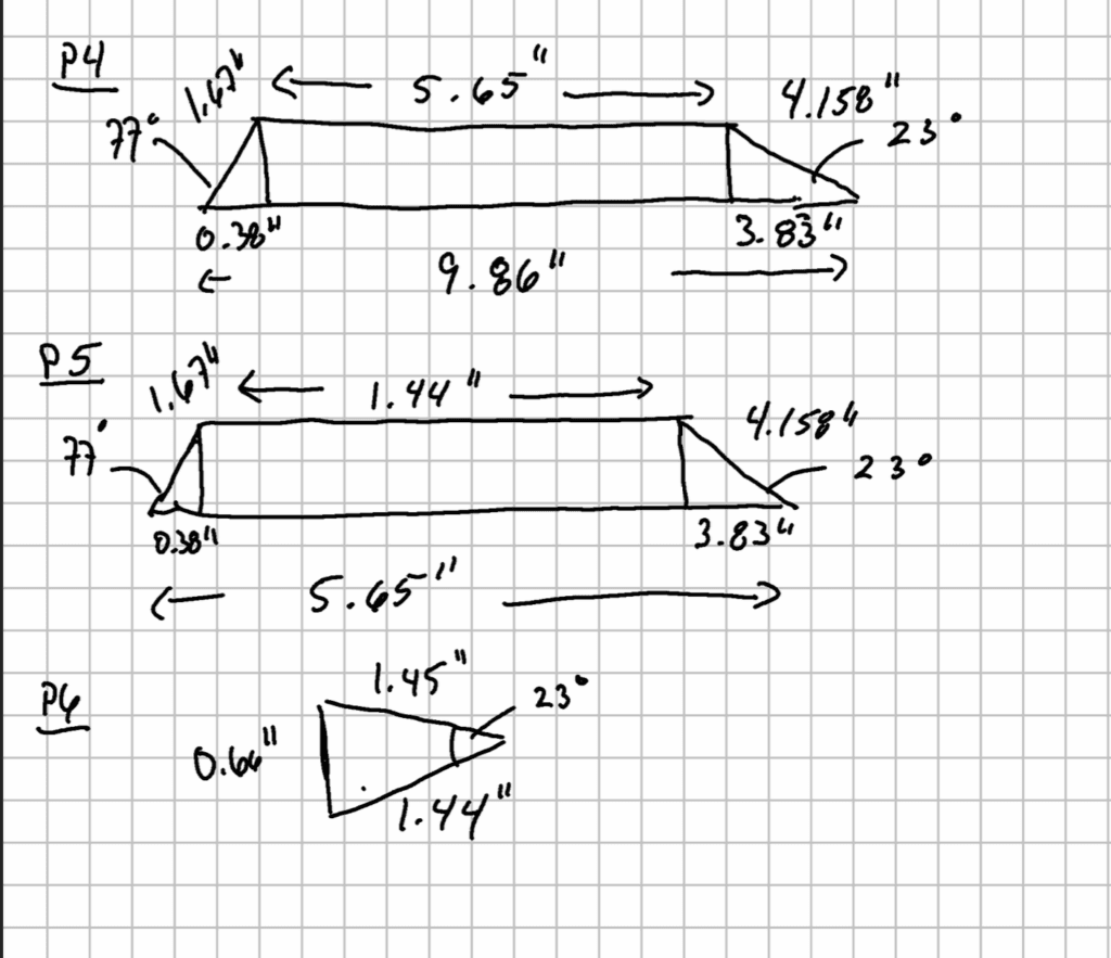
From there, I measured the height of the bearers at the center of the two engine feet. It took me several sets of measures to figure out the actual proper measurements. I did some of them with indirect measurements and trigonometry and I did others with different instruments. I ended up on excel trying to reconcile the measurements, accounting for measurements errors of all the instruments I used. Finally, I ended-up discovering that the laser calibration was malfunctionning in one direction and once that was factored in the measurements errors, every measurements agreed on the dimensions. All of this to say that I took several steps to ensure the design measurement was within the adjustment range of the engine feet. By doing so, I guaranteed myself that any built-in error could be corrected by a few turns of screw on each engine feet. The design for the engine bearers is shown in the pictures below. The first picture shows the overal sideview of the bearers. The other pictures splits the design into pieces of 1 5/8″ x 3 1/2″ (laminated 2″ x 4″).
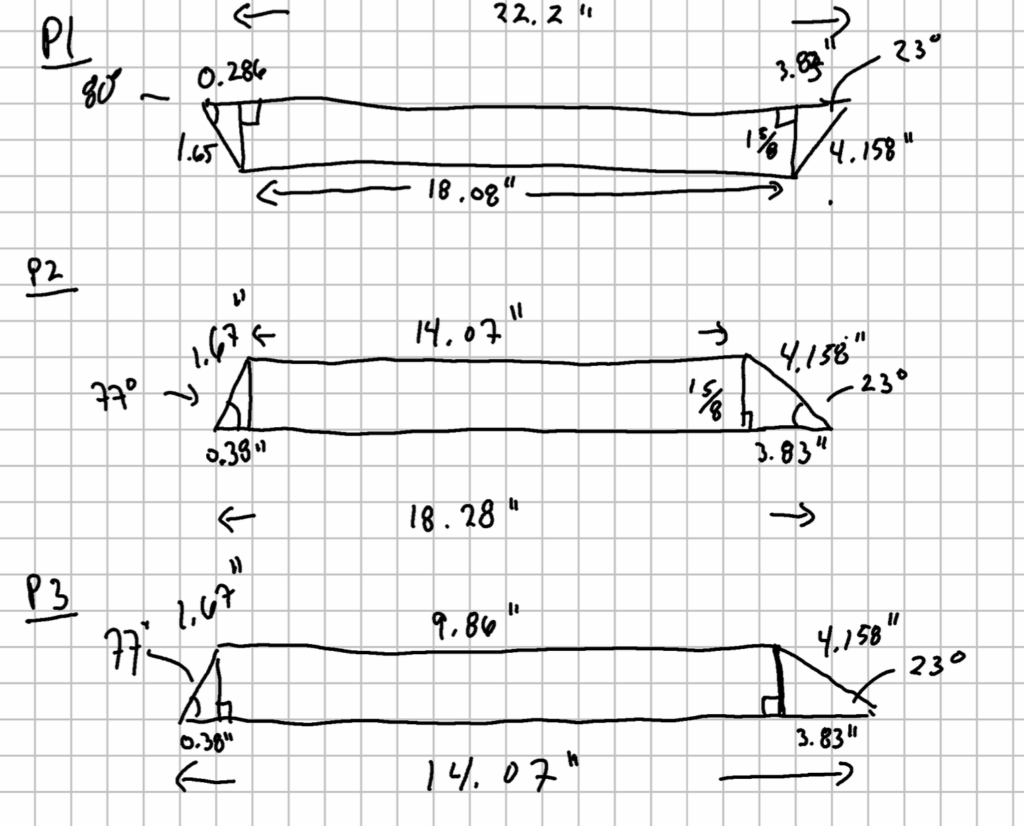
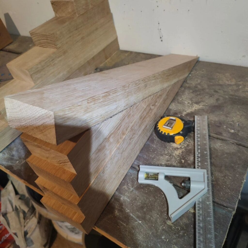
I chose white oakwood for the engine bearers. The logic is to choose a strong wood. It took me two good days to find a supplier, and it took them a week to provide the pieces, so its best to plan ahead. The pieces were screwed together and bonded with wood glue, paying extra attention to not place screws where the engine feets were planned to be. The resulting design is shown in the two pictures below.
Fiberglassing the bearers to the hull was done in two parts. The first part is about filling the gap under the bearers and the hull. This was done in three steps. First layering thickened epoxy (peanut buttery) on the corners of the bearers, both under and on the sides, so as to have a first good layer of epoxy resin. Then, I used polyester resin putty (« thickened polyester resin ») to fill most of what is under the bearer. I then finished with thickened epoxy for the final innermost layer of resin under the bearers. Thus, the underside of the bearers is an « ice cream sandwich » of two sides of thickened epoxy and one center of polyester putty. The whole thing was grinded to offer a smooth surface over which the fiberglass would be laid down.
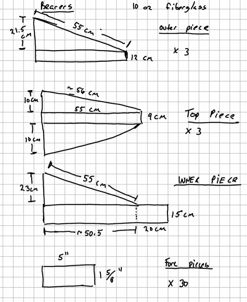
The second part was layering the fiberglass down. In order to have enough surface of contact to the hull, especially on the exterior side of the bearers, I decided to remove the sides of the engine room. The design for the fiberglass pieces is shown in the picture below. It follows the idea exposed in BoatWorks Today’s video on « How to Fiberglass Over Plywood » (see the fiberglass section), that is three pieces of fiberglass that overlap on the plane sides of the bearers: the top piece, the outer piece, and the inner piece. The inner and outer piece of course extends much wider than the bearers themselves, increasing the bond to the hull by a wider surface of contact.
Once the surfaces grinded, cleaned with acetone and the fiberglass mat pieces cutted to the proper dimensions, the bearers where fiberglassed in less than 30 minutes. I used three layers of 10 oz fiberglass mat.
Hindsight is 20/20
If I were to do it again with the same information I had on the engine position, I would probably change three things. First, instead of assembling the oak alltogether prior to its installation, I would through bolt the bottom piece so that the bolts would gel in thickened epoxy. Second, I would use a mold to pour all the thickened epoxy below the bearers in one application. Then, I would assemble the remaining pieces of the engine bearers using glue and screws. That approach would increase the strength of the bond between the hull and the bearers. Third, I would increase the height of the bearers at the fore engine feets by roughly 6 milimeters (a quarter inch) so as to have a better alignment from the bearers themselves. This increase is well within the tolerance factor built in the early measurements, but it would have been better than quarter inch steel plates added during the alignment.
NPT, NPR and Tri-flanged Installs
Knowledge about plumbing standards helps understanding which pieces to order. It further helps separate the signal from the noise in the wide variety of conflicting information received on plumbing. What is described below is mostly a summary of the American Boat and Yacht Council standard (ABYC, 2021). It can be ignored, as some boat manufacturers do, but these standards exists to mitigate risks.
Somewhere between now and the Big Bang, American plumbers figured out it would be useful to have standards regarding threads. They (figuratively) sat down to and came with the American National Standard [for] Pipe Thread. If you ordered two pieces of plumbing that do not fit together, you can be comforted by the fact that it is your fault rather than a lack of standards.
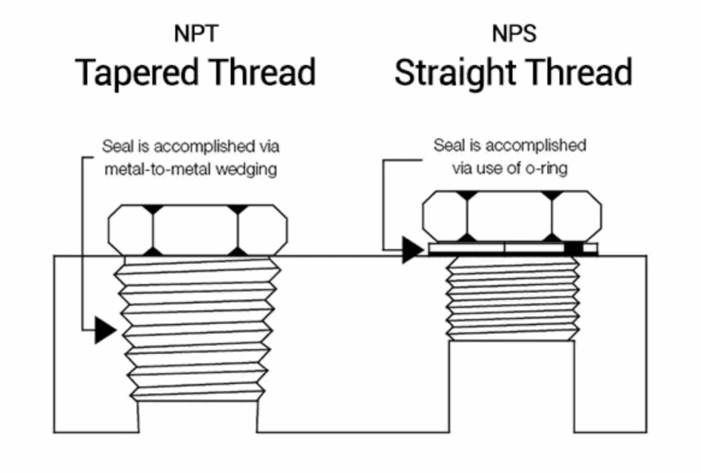
Through-hulls follow the National Pipe Straight (or NPS for short) type (Marine How-To, n.d.). The NPS threads have a constant diameter. The main advantage is that it can be cut at any point and the diameter remains the same. This is ideal for pieces serving different needs in terms of length, as it is the case for through-hulls. After a male NPS thread is cut, it still fits perfectly in its female counterpart, allowing for all the grip that the threads can deliver.
In contrast, the National Pipe Taper (or NPT for short) has an increasing diameter, as a cone. The advantage is to favour the mechanical sealing of the pipes. However, if the male part of an NPT thread is cut, it will no longer fit in its female counterpart. Most pieces of plumbing have NPT threads.
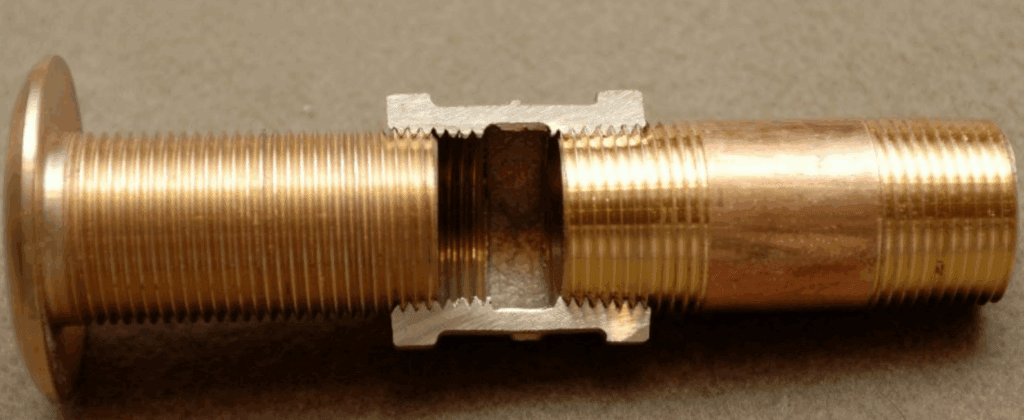
A simple idea, very well understood by insurance companies, is that pieces of different threads standards should not be used in the same connection. In particular, a male NPS through-hull should not be fitted with a female NPT shut-off valve. Because the valve has a conic thread, it will not allow enough turns for the through hull to seal shut (first picture below, borrowd from Marine How-to). This leads to a possible leak or worse, a breakage at the joint. A through hull should go in an NPS female piece… although the rest of the plumbing is designed with NPT threads. This means that the female piece receiving the through-hull must convert to NPT on its male end. Groco does a sell an NPS to NPT converter exactly for that reason. It is also possible to purchase tri-flanged valves with the proper adapter as well.
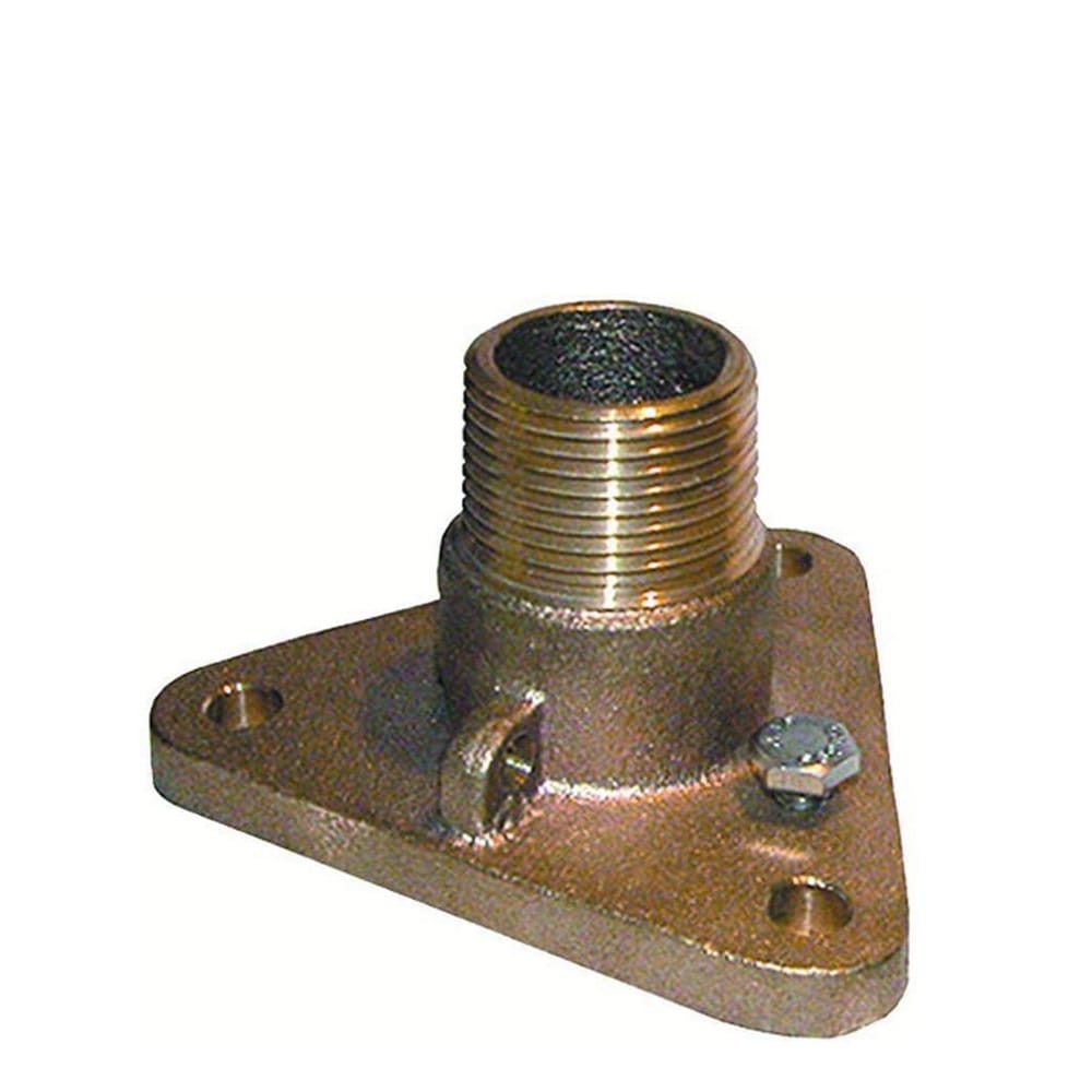
Tri-flanged valves or adapters are also a good idea. As argued by Marine How-to, they prevent the valve for turning around the hull, they are fastened to the hull or to a backing plate and are thus stronger (Marine How-to, n.d.).
Practical Installation
The installation of through-hulls, tri-flanged valves and backing plate is very well explained by AtomVoyager (2019; video below). Watching the video gives a good understanding of pretty much everything needed to perform the install. After fiberglassing the backing plates, at least a full day is required for the epoxy to cure enough to be able to continue the install.
Rudder Design
The rudder design I used is in the picture below. The rudder was manufactured by CCI composite from my measurements (and they produced a profesionnal design, not shown here). They were very patient , professional and they even corrected some of my measurements.
Ex-post, I would only change two things on the design. First, I would increase the rudder post length by one inch (26″ instead of 25″). Second, I would increase the angle of the backside aperture so as the have the backside match the rear line of the hull. The current aperture size tested my patience when dry-fitting the propeller and the rudder. There was not a lot of margin for adjustment! Otherwise, the rudder design works.
Practical repairs or install
Installing or removing a rudder is not rocket science when you understand what to look for. For Alberg 30s, the best material availlable on YouTube is from Sailing Aqua Marie, with a three part video on the rudder (Sailing Aqua Marie, 2022). The owner provides several structural dimensions and some techniques on how to handle repairs. There is also a great video made by Abroad Reach Travel on the rudder removal (Abroad Reach Travel, 2020).
Installing and Fiberglassing the Sterntube
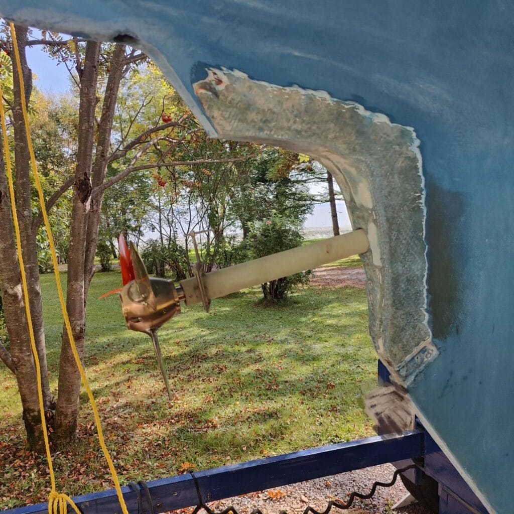
Recall that Jean-du-Sud had no (inboard) power train prior to the engine install. In particular, it had no propeller and thus, no sterntube. So the first practical task was to find the aperture and the former sterntube hole.
When Cortez arrived to the « New World » (America), he ordered that his ships be burned so that there would be no turning back (Smith, 2022). I began the install with grinding the aft part of Jean-du-Sud’s keel so as to find the aperture and the sterntube hole. It was of course a necessary step, but it was also a commitment. I burned my ships!
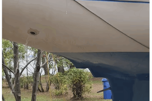
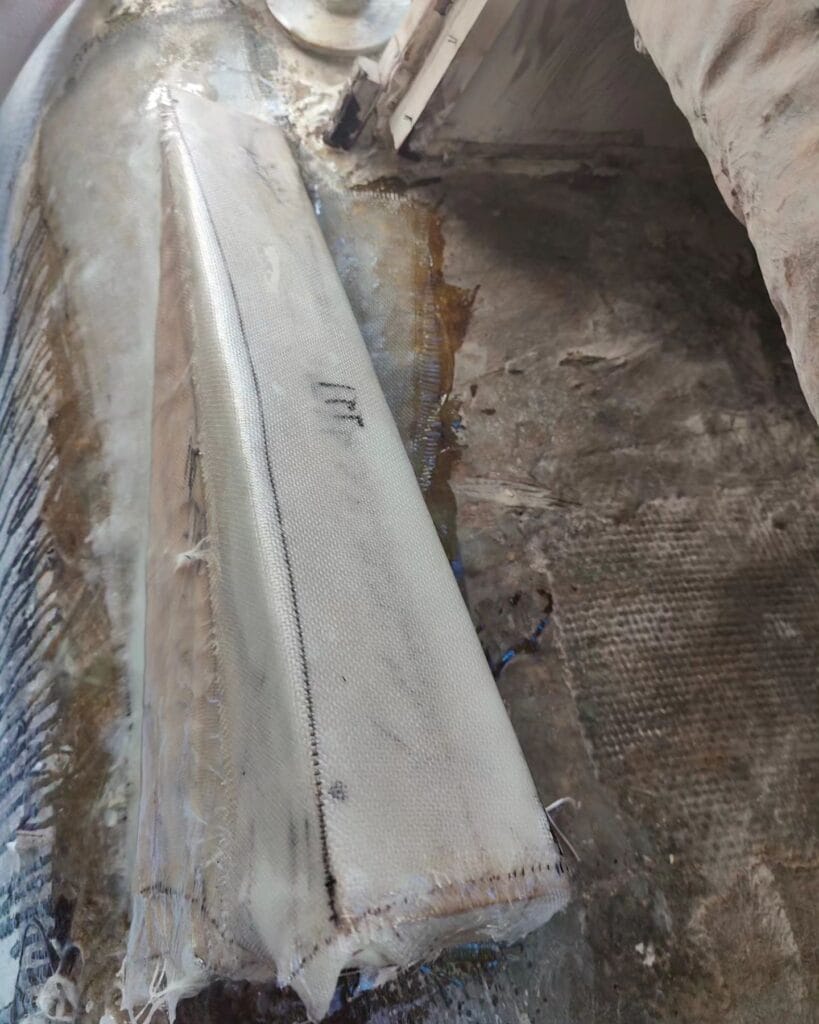
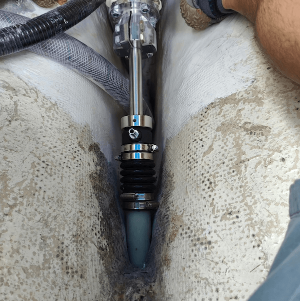
In more practical terms, I had to install a new sterntube. I chose to use a fiberglass model over bronze because of its superior adhesion to the hull. Furthermore, fiberglass does not corrode, reducing the list of future potential problems by one. The sterntube is 18 centimeters long (7 inches), accomodating a one inch diameter shaft. I started with a longer sterntube and cut it to the right dimension once the engine was installed. Only 34 milimeters stem out of the aperture (picture below), meaning that the remaining 14.6 centimeters are inside the hull.
As a part of the whole, I fiberglassed the sterntube after installing the engine on its bearer. It is easier to fiberglass the sterntube with the proper alignment than aligning the engine to the sterntube. From a design standpoint, fiberglassing the sterntube after the engine is installed gives an additional degree of freedom during the alignment. In practice, the shaft just aligns itself on its pivot point and the sterntube follows, greatly reducing the needs for adjustments. So if anyone can do it, I highly recommend the approach.
For fiberglassing the sterntube, the three most useful online sources are from Timothey C. Lackey (2009), from the Practical Sea School (2021; video below) and from Far Reach Voyages (2020). Lackey’s web page was my starting point to understand how to do it and remained my main reference during that part of the install.
There is also a video made by James Frederick (2020) that uses a bronze sterntube. It is not useful from a fiberglass standpoint, but since it is performed on an Alberg 30, it can help get a sense of the dimensions (Frederick, 2020). Finally, Costa Blanca Yacht Services made a video showing how they did a structural repair of a sterntube (Costa Blanca Yacht Services, 2020). The video is pretty instructive, especially for how to think about the finishing coats. That being said, I find that their filling of the sterntube’s surroundings with polyester resin putty to be a risky choice.
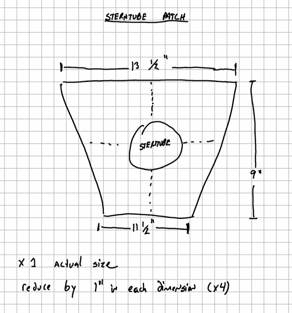
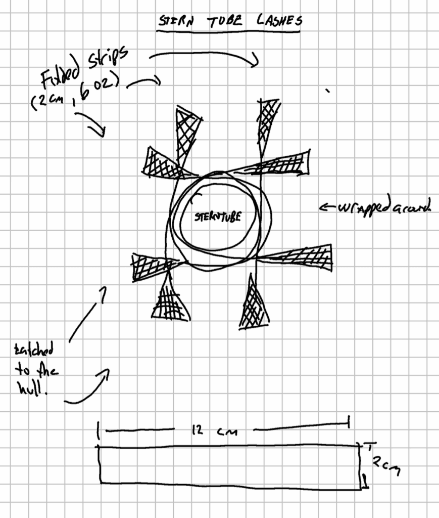
For the exterior fiberflass, I used five pieces of 16 oz cloth as the structural layers to fix the sterntube. The design of the largest piece is shown in the drawing below (first picture of three below). Each other piece has its dimensions reduced by one inch on each side. Each piece was layered in ascending order of size, so that each new layer would overlap the previous one. Between each layer, I added 2 centimeters strips of 6 oz fiberglass around the sterntube, so that the ends of each strip would “latch” onto the hull (see the second picture below). Each strip was latched in a different orientation, so as to increase strength in all directions. I finished the layering with two 6 oz pieces that were one inch larger than the largest 16 oz piece. The final layering is shown in the third picture below.

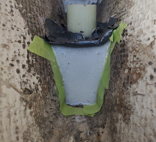
If for some reason the shaft were to jam in the sterntube, there would be a lot of load on these exterior pieces of fiberglass. To reinforce the bond, I decided to pour thickened epoxy on the other side of the hull. I used a cardboard piece reinforced with chicken cage to create a mold where the epoxy would thicken. The length was chosen to guarantee that the seal shaft would have a long enough lip on the sterntube to be firmly attached (pictures below).

Conclusion
I will conclude this text with a counterpoint, detailling the elements of the power train install that I thought would be hard, but turned out to be straightforward. First, the engine alignment is not difficult. As James Frederick pointed out to me, « just go slow ». Once you get a good sense of where to apply pressure on the engine to get it moving, moving it on the bearers is straightforward. I would only say that it helps to do this with someone else. If you have feeler gauges and a second pair of hands, then its just a matter of patience.
Second, finding the sterntube hole is not a big thing either. After a few hours with the grinder, the former aperture was fairly visible and once it was carved, finding the sterntube hole was straightforward. I mention this because prior to physically acquiring the boat, I spent hours looking at techniques on how to bore long holes in a hull. I even looked for renting boring bars and called specialized shops, worrying about boring a long hole at the proper angle. All of these worries vanished in a second when I saw that I could just punch the balsa piece that filled the hole.
Likewise, replacing the cockpit drains was pretty straightforward. It took a week to have the pieces delivered, but the install took less than an afternoon. Easy stuff.
Finally, as the quote states in the introduction of the text, there is no point into getting exact measurements. It may be best to think of good enough measurements as something slightly better than the margin of error generated by the tools you use. In plain terms, there is no point in getting precision up to one sixteenth of an inch if your skillsaw has a blade of one eigth of an inch. Coming from a background of theoritical modeling (i.e. advanced maths), \sqrt{2} and 1.4 are very different numbers. But for boat work, they mean the same thing.
Will the install hold up to expectations? This is certainly the next big test and one of the major reasons I decided to defer my trip down south. If anything were to go wrong, it would be much better to happen closer to my lair. That may very well be a follow-up text that will be written in a year. In the meantime, I will enjoy the work I did and begin thinking about the next project.
Acknowledgements
I am thankful for the help of Julien DT, James Frederick, John Rae and Philip Locker, Chris Lawley, my father and Chris Riedinger for their comments, suggestions and improvements along the final moments of the install. All errors remain my own.
References
Abroad Reach Travel (2020). Bottom Paint and Rudder Shoe | Alberg 30 Refit Episode 11, YouTube Video, retrived online at this url.
American Boat and Yacht Council, Standards List, retrieved online in October 2023 at this url.
AtomVoyager (2019). Installing Groco Seacocks and Backing Blocks, YouTube Video, retrived online in October 2023 at this url.
BoatUS (2012). Polyester or Epoxy resin?, retrieved online in October 2023 at this url.
BoatWorks Today (2022). Epoxy for Beginners, YouTube, retrieved online in October 2023 at this url.
BuyFittingsOnline.com (n.d.). Understanding NPT, NPTF & NPS Thread Connections, retrieved online in October 2023 at this url.
Casey, D. (2005). Complete Illustrated Sailboat Maintenance Manual, McGraw Hill, 892 pages, ISBN 0-07-146284-8.
CompositeWorld (n.d.). Polyester resins: The Basics, retrieved online in October 2023 at this url.
CruisersForum.com (2021). Fiberglass reinforcements to restore an odd engine bed structure, retrieved online in October 2023 at this url.
Elchakany, M., Yang, B. and T. Pham (2023). Mechanical Properties of fiber reinforced polymer (FRP) and steel bars, Chapter 2 of Geopolymer Concrete Structures with Steel and FRP Reinforcements: Analysis and Design, Woodhead Publishing, Pp 75-135, ISBN 9780443188763.
El-Wazery, M.S., El-Elamy, M.I., Zoalfakar, S.H. (2017). Mechanical Properties of Glass Fiber Reinforced Polyester Composites, International Journal of Applied Science and Engineering, 14(3), pp. 121-131.
Far Reach Voyages (2020). Big Changes…Part I: Installing an Inboard Diesel Engine, retrived online in October 2023 at this url.
Fiberglass wharehouse (2022). Polyester resin vs Epoxy resin, retrieved online in October 2023 at this url.
J. Frederick (2020). Installing a New Bronze Stern Tube on an Alberg 30 at The Ventura Harbor Boat Yard, YouTube Video, retrieved online in October 2023 at this url.
T. C. Lackey (2009). Systems: Sterntube and Shafting, The Triton Daysailor Project, retrieved online in October 2023 at this url.
Mantovani, D.P., Rohen, L.A., Neves, A.C.C., Vieira, J.S., Pontes, L.A.P., Viera, C.M.F, Margem, F.M. and S.M. Monteiro (2017). Comparative Analysis of the Tensile Properties of Polyester to Epoxy Matrixes Composites Reinforced with Hemp Fibers, International Workshop Advances in Cleaner Production Proceedings, retrived online in October 2023 at this url.
Marine How-To (n.d.). Seacock and Thru-hull: A Primer, retrieved online in October 2023 at this url.
Practical Sea School (2021). Replacing the Stern Tube – Part 1, YouTube video, retrieved online in October 2023 at this url.
Sailing Aqua Marie (2022). Episode 18 – Pulling the Rudder, YouTube video, retrieved on October 2023 at this url.
D. Smith (2022). Sometimes It’s Best to Burn Your Ships, retrieved online in October 2023 at this url.
SP Systems (n.d.). The Advantages of Epoxy Resin versus Polyester in Marine Composite Structures, retrieved online in October 2023 at this url.
Wikipedia (n.d.). Polyester resins, retrieved online in October 2023 at this url.
________ (n.d.). Epoxy, retrieved online in October 2023 at this url.
________ (n.d.). Fiberglass, retrieved online in October 2023 at this url.